PETROCAT equipment
Equipment
PETROCAT has access to the following equipment of LEFH
Pilot Plant Units
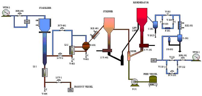
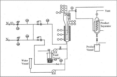
 A schematic diagram of the fully automated FCC pilot plant is shown in figure 1. Preheated gas oil feed flows in the bottom of a riser, where it is mixed with hot regenerated catalyst. In the riser the reactions take place and at the riser exit, the mixture flows into the stripper vessel where the separation of gases from the solid catalysts occurs. The solids flow through the spent catalyst lift line and they return to the reactor bottom following regeneration.
The reaction products, from the stripper exit, flow through a heat exchanger and then after their temperature is reduced to 20°C in order to condense the heavier products. Then the mixture is led to a stabilizer column for better separation of liquid and gaseous products. The specifications of CPERI pilot plant are shown in table 1.
| Table 1 Pilot plant specifications and operating conditions | ||
|
1 |
Riser id (mm) and height (cm) |
7.08 and 165 |
|
2 |
Regenerator bed id (mm) and height (cm) |
77.9 and 72 |
|
3 |
Stripper id (mm) and height (cm) |
26.6 and 150 |
|
4 |
Lift line id (mm) |
9.45 |
|
5 |
Maximum liquid feed rate, gr/min |
25 |
|
6 |
Catalyst circulation rate, gr/min |
35 and 500 |
|
7 |
Maximum reactor Pressure, atm |
3.3 |
|
8 |
Max riser temperature, deg C |
590 |
|
9 |
Max stripper temperature, deg C |
590 |
|
10 |
Max regenerator temperature, deg C |
700 |
|
11 |
Catalyst inventory, gr |
4500 |
Two steamers unit are available in LEFH for fresh FCC catalyst deactivation. Except for steaming the units can be used and as calcination units for the evaluation of equilibrium FCC catalysts. Each unit consists of a quartz fluid bed reactor heated by a 3-zone furnace. Temperature control is achieved with measurements from thermocouple in the catalyst bed. The dimensions of the one steamer are 75cm height and 6cm diameter and accepts 150g of fresh catalyst. The second steamer accepts 3-5 Kg of catalyst. The usage of each unit depends on the forthcoming step for catalyst evaluation (MAT or FCC pilot plant respectively). The fluidization stream is steam and the temperature 1450oF, when the unit is used as a steamer. During the calcination procedure the fluidization stream is air and the temperature applied in the unit is 1005oF. The units are fully automated and steaming or calcination can be terminated after a desired period of time.
 The reaction unit consists of the feed gas system, a fixed- and a fluidized-bed reactor, two three-zone furnaces controlled by PID controllers, one for each type of reactor and the gas analysis system. The fixed- and fluidized-bed reactors are connected in series and can be bypassed by the feed. In the fixed-bed experiments the flow rate of the inlet gas was 500 ml/min and the reactor loading was 2 g. In the fluidized-bed experiments the flow rate of the inlet gas was 1000 ml/min and the reactor loading was 10 g. Samples from the exit gas stream were analyzed to identify the gas products during regeneration using series of gas analyzers.
The CPERI cyclic deactivation unit (CDU), designed by Xytel, is fully computerized and simulates satisfactory the E-cats by depositing metals on FCC catalysts. This laboratory method is considered to be the most widely acceptable for FCC catalyst aging. The CDU mimics the FCC catalyst deactivation the catalyst in repeat cycles: cracking, stripping and regeneration. LEFH follows a specific protocol where the complete CDU run consists of 54 cycle, of which each cycle follows a cracking, a stripping and a regeneration step. Each cycle holds for about 60 min.
The cracking step is taken place at 500°C for 50s. The stripping is carried out with nitrogen for about 180 sec at 500 °C. The regeneration holds for 2580 sec at 788 °C. The regeneration is achieved by a mixture of O2 and N2.
 The unit process specifications are reported in table 1. The unit consists of the following modules:
Gas delivery modules: This part of the system contains three (3) independent gas feed modules with all necessary equipment. For this system hydrogen, nitrogen, of a mix of hydrogen/H2S can be used as feed gas.
Liquid delivery module: Oil is contained in a nitrogen-blanketed vessel, which is situated on a weigh scale. This feed vessel is provided with electrical heating that is under automatic temperature control by the computer. The pre-sulfhiding liquid is contained in a nitrogen-blanketed vessel.
Gas outlet module: Initial part of this module is the pressure control section, which maintains the required reactor pressure. A by-pass is installed for atmospheric operation of the installation. In this case the outlet lines, incl. Pressure control section, are heat traced and insulated. The outlet vent is connected to a wet test meter to measure the outlet flow of the system.
Separation and liquid outlet module: A pipe in pipe cooler cools the reactor outlet product. The separator has a narrow electrically heated liquid-part and wide water cooled gas-part. Product is collected in a heated vessel, which is located on a weigh scale. Normally the vessel is vented to the gas module.
| Table 1: HDS-1 - Process Specifications | ||
|
1 |
Number of reactor in series |
2 |
|
2 |
Reactor Volume, CC |
265 |
|
3 |
Reactor Diameter, inches |
2 |
|
4 |
Reactor Length, inches |
75 1/2 |
|
5 |
Catalyst bed length, inches |
18 |
|
6 |
Operating pressure, barg |
280 |
|
7 |
Operating temperature, max ° C |
550 |
|
8 |
Liquid Feed Rate, ml/h |
30-600 ml/h |
|
9 |
Gas Rate, Nl/h |
100-1000 |
Bench Scale Units
The SCT-MAT reactor is made by Pyrex glass and it is heated by a three-zone furnace. Preheated feed (60°C) is injected into the reactor through an oil capillary heated only by the oven. For this injection a special motor pump is used. The reactor consists of an annular bed where the catalyst is diluted with inert glass beads. The vapor products of the cracking are cooled to 0 °C at the reactor exit where part of them are condensed and collected in a specially designed high volume liquid receiver. The remaining not condensed gaseous products are led to gas collection system (cylinders) and are collected by water displacement. Following the oil injection, N2 flows into the reactor in order to drive the products along the reactor.
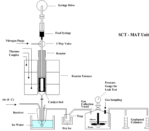
The gaseous products are analyzed at a specially designed GC called Refinery Gas Analyzer (HP-5890). The gasoline produced is analyzed by Capillary Gas Chromatography (HP 5880 A). The weight of coke, deposited on the catalyst, is measured by an Elemental Analyzer (Leco CHN-800 model).
One of the most important parameters which determine the yield, the quality of FCC products and in general the competitiveness of FCC unit is the catalyst type. It is, therefore, important to be able to predict the effectiveness of FCC catalyst with reliable laboratory tests. With these test the refineries can choose the most satisfactory catalyst.
Two steamers unit are available in LEFH for fresh FCC catalyst deactivation. Except for steaming the units can be used and as calcination units for the evaluation of equilibrium FCC catalysts. Each unit consists of a quartz fluid bed reactor heated by a 3-zone furnace. Temperature control is achieved with measurements from thermocouple in the catalyst bed. The dimensions of the one steamer are 75cm height and 6cm diameter and accepts 150g of fresh catalyst. The second steamer accepts 3-5 Kg of catalyst. The usage of each unit depends on the forthcoming step for catalyst evaluation (MAT or FCC pilot plant respectively). The fluidization stream is steam and the temperature 1450oF, when the unit is used as a steamer. During the calcination procedure the fluidization stream is air and the temperature applied in the unit is 1005oF. The units are fully automated and steaming or calcination can be terminated after a desired period of time.
A large Cyclic Propylene Steaming (CPS) deactivation unit is available in LEFH for FCC catalyst deactivation. The unit is fully automated and consists of a metal fluid bed reactor heated by a 3-zone furnace. Temperature control is achieved with measurements from thermocouple in the catalyst bed. The CPS unit accepts about 5 Kg of FCC catalyst. Metals are deposited on the catalysts following a standard wet impregnation method. Then the catalyst is loaded in the CPS unit for the deactivation. A special protocol is applied in the unit using alternate oxidation-reduction cycles. The oxidation takes place with a mixture of air while the reduction with a mixture of propylene. Steam is always added in the unit for all cycles.
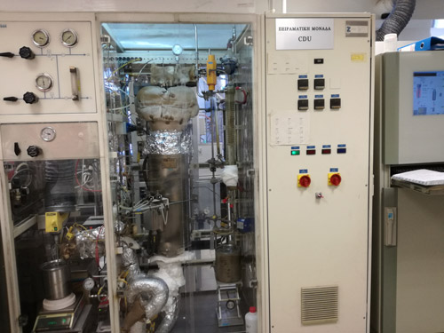
The CPERI cyclic deactivation unit (CDU), designed by Xytel, is fully computerized and simulates satisfactory the E-cats by depositing metals on FCC catalysts. This laboratory method is considered to be the most widely acceptable for FCC catalyst aging. The CDU mimics the FCC catalyst deactivation the catalyst in repeat cycles: cracking, stripping and regeneration. LEFH follows a specific protocol where the complete CDU run consists of 54 cycle, of which each cycle follows a cracking, a stripping and a regeneration step. Each cycle holds for about 60 min.
The cracking step is taken place at 500°C for 50s. The stripping is carried out with nitrogen for about 180 sec at 500 °C. The regeneration holds for 2580 sec at 788 °C. The regeneration is achieved by a mixture of O2 and N2.
 The reaction unit consists of the feed gas system, a fixed- and a fluidized-bed reactor, two three-zone furnaces controlled by PID controllers, one for each type of reactor and the gas analysis system. The fixed- and fluidized-bed reactors are connected in series and can be bypassed by the feed. In the fixed-bed experiments the flow rate of the inlet gas was 500 ml/min and the reactor loading was 2 g. In the fluidized-bed experiments the flow rate of the inlet gas was 1000 ml/min and the reactor loading was 10 g. Samples from the exit gas stream were analyzed to identify the gas products during regeneration using series of gas analyzers.
Analytical Laboratory for Catalyst Characterization
-
BET method: N2 physisorption for specific surface areas quantification and pore size distribution
-
XRD: X-Ray Diffraction for crystal phases detection and Unit Cell Size of zeolites measurement
-
ICP-AES: Inductively Coupled Plasma with Atomic Emission Spectroscopy for elementary analysis on solids and liquids
-
SEM-EDS: Scanning Electron Microscopy with Energy Dispersive Spectroscopy for surface morphology observation and elemental distribution on solid particles (mapping, linescans)
-
HR-TEM: High Resolution Transmission Electron Microscopy for identification of atomic structure and elemental coordination in specific parts of catalyst particles
-
FTIR: Fourier Transform Infrared Spectroscopy in combination with Pyridine adsorption for acidity quantification of solid catalysts
-
TPX: Temperature Programmed processes like reduction, oxidation and NH3 or CO2 desorption for reducibility studies, oxidative studies and acidity or basicity quantification on solid catalysts respectively. Detection via Mass Spectroscopy (MS)
-
TGA: Thermogravimetric Analysis, Differential Scanning Calorimetry (DSC) and Differential Thermal Analysis (DTA) of solid materials
-
LECO: Elemental analysis mainly for Carbon content on solid catalysts and liquid samples
-
PSD: Particle Size Distribution with laser diffraction
Analytical Laboratory for Fuels Characterization
ANALYTICAL EQUIPMENT AND METHODS
Accurate and precise analyses provide the cornerstone for successful research and catalyst evaluation studies. CPERI possess a modern fully equipped laboratory (run under a Laboratory Information Management System, LIMS), which employs ASTM methodologies and is capable of performing a total of 55 different analyses. (See analytical services offered below for details)
CPERI's analytical services have been certified and approved by Lloyd's Register Quality Assurance to conform to the BC EN ISO 9001 quality management system standard and ISO 17025 quality policy, with respect to the provision of laboratory inspection services related to fuel content and solid characterization.
The laboratory is regularly audited as per ISO requirements.
ANALYTICAL METHODS
|
Description of analysis
|
Method analysis
|
Type of Instrument
|
| Qualitative analysis of organic compounds by GC/MS |
--
|
Hewlett-Packard GC 5890 series II MS ENGINE 5989 |
| Quantitative analysis of hydrocarbons (parafins, aromatics, etc.) by GC/MS. |
--
|
Hewlett-Packard GC 5890 series II MS ENGINE 5989 |
| Determination of Benzene content of Gasoline by GC/MS |
ASTM D 5769/98
|
Hewlett-Packard GC 5890 series II MS ENGINE 5989 |
| Determination of oxygenates in Gasoline by GC/MS |
--
|
Hewlett-Packard GC 5890 series II MS ENGINE 5989 |
| Qualitative analysis of biomass compounds by GC/MS | Hewlett-Packard GC 5890 series II MS ENGINE 5989 | |
| Determination of phenols compounds by GC/MS | Hewlett-Packard GC 5890 series II MS ENGINE 5989 | |
| Determination of terpens in Essential Oils by GC/MS | Hewlett-Packard GC 5890 series II MS ENGINE 5989 | |
| Hydrocarbon Type Analysis in Naphtha (PIONA analysis) and Calculation of RON by GC |
ASTM D 5134
|
Hewlett-Packard GC 5880A |
| Determination of Hydrocarbons in Naphtha by GC |
ASTM D 5134
|
Hewlett-Packard GC 5880A |
| Hydrocarbon Type Analysis in Gasoline fractions of Petroleum (PIONA analysis) and Calculation of RON by GC |
ASTM D 5134
|
Hewlett-Packard GC 5880A |
| Determination of Hydrocarbons in Gasoline fractions of Petroleum by GC |
ASTM D 5134
|
Hewlett-Packard GC 5880A |
| Quantitative analysis of flue gases (CO2, CO, O2 ) by GC. | Hewlett-Packard GC 5890 series II | |
| Quantitative analysis of gases (H2, N2, O2) by GC | Hewlett-Packard GC 5890 series II | |
| Quantitative analysis of light hydrocarbons (CH4 - C6 ) by GC |
--
|
Hewlett-Packard GC 5890 series II |
| Boiling Range Distribution of Gasoline by GC |
ASTM D 3710
|
Varian 3400, Hewlett-Packard GC 5890 series II |
| Boiling Range Distribution of Petroleum Fractions by GC |
ASTM D 2887
|
Varian 3400, Hewlett-Packard GC 5890 series II |
| Determination of Ethanol in Aqueous Solutions by Headspace/GCMS | Hewlett-Packard Headspace Inj7694 GC 5890 series IIMS ENGINE 5989 | |
| Sulphur Compounds in Light Petroleum Liquids by GC/SCD |
ASTM D 5623
|
Hewlett-Packard GC 6890 plusSievers 355 |
| Sulphur Compounds in Gasoline Range of Petroleum Liquids by GC/SCD |
ASTM D 5623
|
Hewlett-Packard GC 6890 plusSievers 355 |
| Paraffin, Naphthene and Aromatic Hydrocarbon Type Analysis (PNA, PIONA, PIANO, PONA) in Petroleum Distillates through 200oC by multi-GC |
ASTM D 5443
|
Analytical Controls PIONA/PREF |
| Simulate Distillation of Petroleum Fractions by GC |
ASTM D 2887
|
AC SimDis |
| Distillation of Petroleum products at atmospheric pressure |
ASTM D 86
|
D86-ISL |
| Distillation of petroleum products at reduced pressure |
ASTM D 1160
|
D1160-ISL |
| Evaluation of crude oil by distillation |
ASTM D 2892
|
D2892-Petrotest |
| Determination of vapour pressure of petroleum products |
ASTM D 5191
|
CCA-VP-Grabner |
| Determination of density and specific gravity |
ASTM D 4052
|
DMA 48-PAAR |
| Determination of heat of combustion |
ASTM D 4809
|
1261PAAR |
| Determination of sulphur ( % w/w) in petroleum fractions |
ASTM D 4294
|
SLFA800 Horriba |
| Determination of sulphur ( % w/w) in petroleum fractions |
ASTM D 5453
|
ANTEK7000/9000 |
| Determination of total nitrogen (%w/w) |
ASTM D 5762
|
ANTEK7000/9000 |
| Determination of viscosity in petroleum products |
ASTM D 445
|
TV 2000 Petrotest |
| Determination of micro carbon residue in liquids and solids products |
ASTM D 4530
|
MCRT130-Petrotest |
| Determination of refractive index |
ASTM D 1218
|
ABBEBellingham & StanleyLTD |
| Determination of mercaptans |
ASTM D 3227
|
751 GPD TitrinoMetrohm |
| Determination of Bromine Index |
ASTM D1491
|
751 GPD TitrinoMetrohm |
| Determination of Bromine Number |
ASTM D1159
|
751 GPD TitrinoMetrohm |
| Quantitative determination of aromatics in Diesel |
IP 391/95
|
Hewlett-Packard 1100 |
| Determination of flash point |
ASTM D 93
|
93 5G ISL |
| Determination of pour point |
ASTM D 97
|
CPP97-2 ISL |
| Determination of cloud point |
ASTM D 2500
|
CPP97-2 ISL |
| Determination of cold filter plugging point |
IP 309/83
|
CPP97-2 ISL |
| Determination of quinizarin in gasoline and diesel by UV |
State Ch. Lab.
|
Helios Unicam |
| Determination of furfural by UV |
pr EN 214
|
Helios Unicam |
| Elementary analysis by CHNS |
-
|
LECO 800/932 |
| Colour Determination |
ASTM D 1500
|
Lovibond Seta Stanhope |
| Total Sediment |
ASTM D4870
|
Seta Stanhope |
| Oxidation Stability Of Gasoline |
ASTM D525
|
Seta Stanhope |
| Copper Corrosion |
ASTM D130
|
Seta Stanhope |
| Oxidation Stability of Diesel |
ASTM D2274
|
Seta Stanhope |
| Aniline Point |
ASTM D611
|
Seta Stanhope |
| Existent Gum |
ASTM D381
|
Seta Stanhope |
| Water & Sediment |
ASTM D1796
|
6K-15-Sigma |
| Cetane Number Calculated |
ASTM D976
|
- |
| Determination of aromatics and non-Aromatics fractions of High boiling point Oil fractions with Column Chromatography |
ASTM D 2549
|
- |